Three processes of GMT materials:Wet Process、Dry Process、Fluidized Bed Process
1.1 Wet Process
Also known as the papermaking process, the wet process involves the following steps【Figure 1】: feeding materials, mixing and flocculating, settling, vacuum forming, moisture removal, heating and plasticizing, shaping and compounding, and cutting.
Process: Short-cut glass fibers and an additive suspension (resin, emulsifiers, etc.) are mixed and then settle onto a moving screen with a vacuum system to form a base felt. This felt is then dried, heated to melt the resin, and finally compounded with non-woven fabric and adhesive film before being cut into sheets.
Advantages: This method allows the glass fibers to be fully separated into single filaments and ensures good impregnation by the resin.
Disadvantages: The process is only suitable for glass fibers 50-80mm in length, and it involves high equipment costs and significant energy consumption.
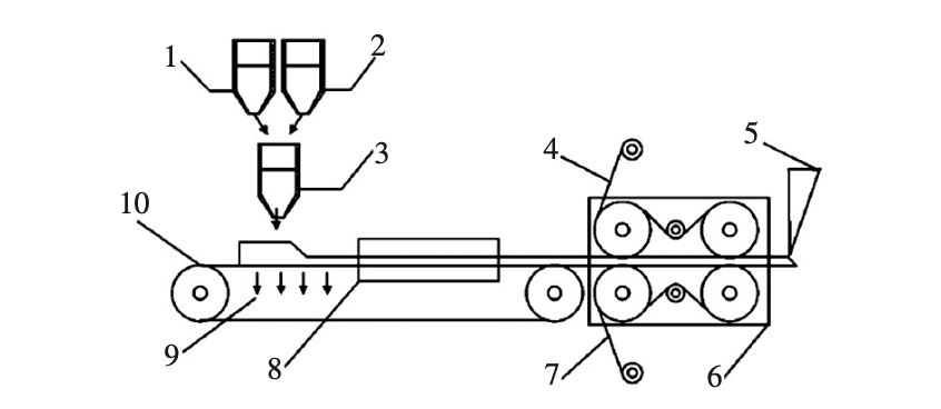
Figure 1: Schematic Diagram of Wet-laid Process Flow and Equipment Structure
- Chopped Glass Fiber-Containing Vessel
- Resin, Emulsifier, and Other Additives Suspension Liquid-Mixing Vessel
- Glass Fiber and Suspension Liquid-Mixing Vessel
- Non-woven Fabric
- Sheet Cutting
- Shaping System
- Adhesive Film
- Heating Furnace
- Vacuum System
- Conveyor Wire Mesh
1.2 Dry Process
Developed from non-woven fabric production techniques, the dry process is also called the carding process.【Figure 2】
Process: Glass fibers are mixed, opened, and carded into single filaments, then blended with hot-melt fibers. This mixture is formed into a web, layered into a base felt, and reinforced with needle punching. The felt is then heated, plasticized, and compounded with non-woven fabric and adhesive film before being cooled and cut.
Advantages: It can process longer fibers (100-150mm) and is environmentally friendly as it produces no waste gas or water.
Disadvantages: The carding process can damage the fibers, reducing their effective length to 50-80mm. The resulting GMT sheets have noticeable anisotropy, meaning their mechanical properties differ significantly in the longitudinal and transverse directions19. To achieve desired mechanical performance, a higher resin content is often needed, which increases costs.
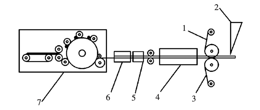
Figure 2: Schematic Diagram of Dry-laid Process Flow and Equipment Structure
- Adhesive Film
- Sheet Cutting
- Non-woven Fabric
- Heating Furnace
- Needle Punching Machine
- Web Spreading Machine
- Fiber Mixing and Carding System
1.3 Fluidized Bed Process
This is a newer technique that uses air as a fluidizing medium.【Figure 3】
Process: Hot air, glass fibers, and resin powder are fed into a fluidized bed and mixed thoroughly by a stirring paddle. This mixture is then sprayed onto a conveyor belt to form a base felt, which is compounded with non-woven fabric and adhesive film, then cold-pressed and cut.
Advantages: This method achieves a thorough pre-mixing of resin powder and individual glass fiber filaments. It is environmentally friendly, producing no toxic or harmful waste.
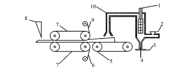
Figure 3: Schematic Diagram of Fluidized Bed Process Flow and Equipment Structure
- Stirring Paddle
- Resin Powder Inlet
- Fluidizing Air Inlet
- Glass Fiber and Spouting Gas Inlet
- Mesh Conveyor Belt
- Non-woven Fabric Setting
- Setting Steel Belt
- Sheet Cutting
- Adhesive Film
- Guiding and Conveying Pipeline
Recent advancements in dry processing include using air pressure to form the web, creating a uniform, three-dimensional fiber structure that improves GMT performance. Another development involves using static electricity to impregnate the fiber mat with resin powder, ensuring more uniform distribution, reducing resin usage and cost, and enhancing material properties.